Giá:
2,316,100 VNĐ
(Giá chưa bao gồm VAT )
Bảo hành: 12 (Tháng)
Tình trạng:
Hàng mới
Nhóm: Thiết bị wifi -» Accessories
Trong kho:
Còn hàng - 1 Cái
Xuất sứ: Chính Hãng
Chi tiết
Thông số kỹ thuật
Download
Phản hồi khách hàng
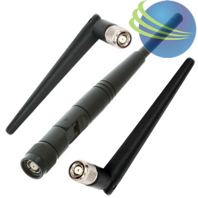
Antenna type : Dipole
Operating frequency range : 2.4- to 2.84-GHz
Environment : Indoor/outdoor
VSWR : Less than 2:1, 1.5:1 nominal
Gain : 5.2 dBi
Polarization : Linear, vertical
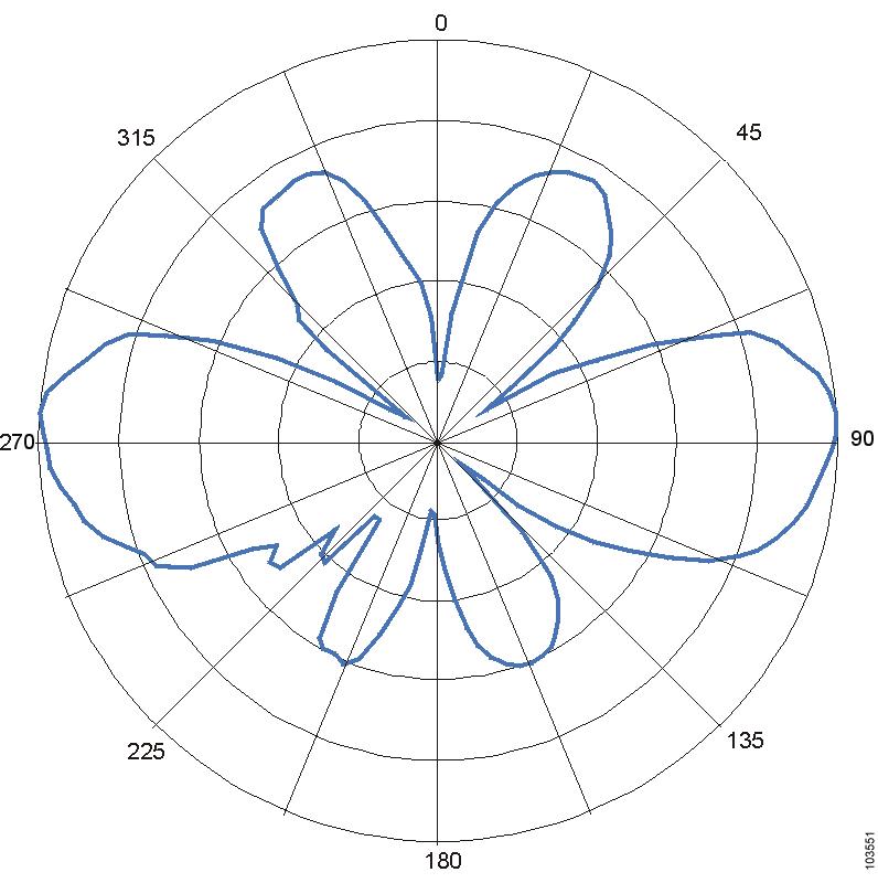
E-Plane (3dB bandwidth) : Omnidirectional
Learn more about the Cisco Systems, Inc. AIR-ANT2506
Model
Spec
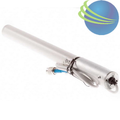
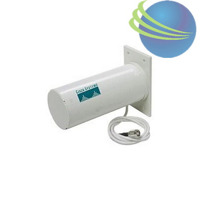
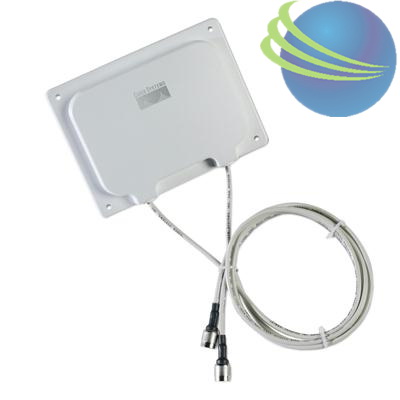
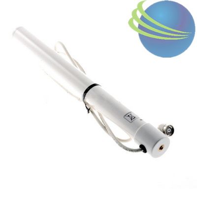
Cisco Aironet Omnidirectional Mast Mount Antenna (AIR-ANT2506)
This document outlines the specifications, describes the omnidirectional mast mount antenna, and provides instructions for mounting it. Designed for WLAN applications in the 2.4- to 2.5-GHz frequency range, the antenna has a nominal gain of 5.2 dBi and is typically mounted indoors or outdoors on a mast. The antenna is compatible with Cisco Aironet radio products utilizing a reverse polarity TNC (RP-TNC) connector.
The following information is provided in this document.
This antenna is compatible with any 2.4-GHz Cisco Aironet radio device with an RP-TNC connector.
Installation Notes
General Installation Instructions for Mast Mounted Antennas
Caution For outside installations, make sure you do not mount the antenna upside down or block the bottom of the antenna at the cable exit. The correct mounting position is with the cable pointing down (towards the ground) so that any moisture will drain through the antenna drain holes. The antenna ships with a yellow mounting instruction label temporarily attached to the antenna radome.
The following instructions are common to most mast mounted installations.
1. Assemble your new antenna on the ground at the installation site.
2. Attach the antenna to the mast and connect its coaxial cable while you are on the ground.
3. Make sure the mast doesn't fall the "wrong way" should you lose control as you raise or take down the mast. Use a durable non-conductive rope secured at each two foot level as the mast is raised. Have an assistant tend the rope, ready to pull the mast clear of any hazards (such as power lines) should it begin to fall.
4. Use the mounting bracket provided with the antenna.
5. If the installation will use guy wires:
a. Install guy anchor bolts.
b. Estimate the length of guy wire and cut it before raising the mast.
c. Attach guy wires to a mast using guy rings.
6. Carefully connect the antenna and mast assembly to its mounting bracket and tighten the clamp bolts.
a. In the case of a a guyed installation, you must have at least one assistant to hold the mast upright while the guy wires are attached and tightened to the anchor bolts.
7. Attach the provided self-adhering "DANGER" label at eye level on the mast.
8. Install ground rods to remove any static electricity buildup and connect a ground wire to the mast and ground rod. Use ground rods designed for that purpose, not a spare piece of pipe.
Grounding the Antenna
Follow these guidelines to ground the antenna in accordance with national electrical code instructions.
1. Use No. 10 AWG copper or No. 8 or larger copper-clad steel or bronze wire as ground wires for both mast and lead-in. Securely clamp the wire to the bottom of the mast.
2. Secure the lead-in wire to a lightning arrestor and mast ground wire to the building with stand-off insulators spaced from 4 feet (1.2 meters) to 8 feet (1.8 meters) apart.
3. Mount the lightning arrestor as close as possible to where the lead-in wire enters the building.
4. Drill a hole in the building's wall as close as possible to the equipment to which you will connect the lead-in cable.
Caution There may be wires in the wall. Make sure you determine the place you intend to drill the hole is clear of any any obstructions or other hazards.
5. Pull the cable through the hole and form a drip loop close to where it enters the building.
6. Thoroughly waterproof the lead-in area.
7. Install a static electricity discharge unit.
8. Connect the lead-in cable to the equipment.
Choosing a Mounting Location
The location of the antenna is important. Objects such as metal columns, walls, etc. will reduce efficiency. Best performance is achieved when transmit and receive antennas are mounted at the same height and in a direct line of sight with no obstructions. If this is not possible and reception is poor, you should try different mounting positions to optimize reception.
The antenna is designed to create an omni-directional broadcast pattern. To achieve this pattern, the antenna should be mounted clear of any obstructions to the sides of the radiating element. If the mounting location is on the side of a building or tower, the antenna pattern will be degraded on the building or tower side.
Site Selection
Before attempting to install your antenna, think where you can best place the antenna for safety and performance.
Follow these steps to determine a safe distance from wires, power lines, and trees.
Step 1 Measure the height of your antenna.
Step 2 Add this length to the length of your tower or mast and then double this total for the minimum recommended safe distance.
Caution If you are unable to maintain this safe distance, stop and get professional help.
Generally, the higher your antenna is above the ground, the better it performs. Good practice is to install your antenna about 5 to 10 feet (1.5 to 3 meters) above the roof line and away from all power lines and obstructions. If possible, find a mounting place directly above your wireless device so that the lead-in cable can be as direct as possible.
Tools and Equipment Required
To install the antenna, you will need the following tools and equipment.
•A standard screwdriver
•A standard hose clamp (shipped with your antenna)
Note This list does not include the tools and equipment required to assemble and erect the tower, mast, or other structure you intend to mount your antenna on.
The following sections contain procedures for installing the antenna. Choose the procedure that applies to your situation. Use figure 1 as a guide.
Mounting the Antenna
The antenna is provided with a mounting kit consisting of a mounting bracket and hose clamp. This kit allows you to mount the antenna to masts from 1.25 inches (3.2 centimeters) to 2 inches (5.1 centimeters). Cisco recommends that a 1.5 inch (3.8 centimeter) or larger tubing mast be used.
The antenna is vertically polarized. Since the antenna has vertical gain, it is very important to mount the antenna in a vertical (not leaning) position for optimal performance.
Follow these steps to mount the antenna on a mast.
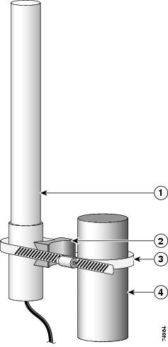
Step 1 Position the antenna, mounting bracket, and hose clamp on the mast as shown in figure 1.
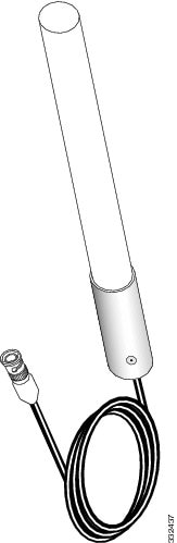
Figure 1 Antenna Mounting Details
1
Antenna
2
Mounting bracket
3
Hose clamp
4
Mast
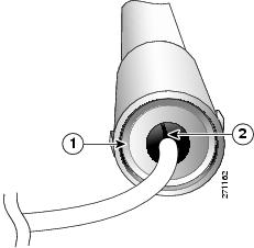
Caution For outside installations, make sure you do not mount the antenna upside down or block the bottom of the antenna at the cable exit. The correct mounting position is with the cable pointing down (towards the ground) so that any moisture will drain through the antenna drain ring. The antenna ships with a yellow mounting instruction label temporarily attached to the antenna radome.
Figure 2 Antenna Drain Details
1
Drain ring
2
Antenna cable
Step 2 Align the antenna so that the metal base is even with or above the top of the mast tubing.
Step 3 Tighten the hose clamp until the antenna is secure on the mast.
Step 4 Connect the antenna coaxial cable to the lead-in cable.
Step 5 Remove the yellow mounting instruction label.
Step 6 If the installation is outdoors, weatherproof the antenna connection (the point at which the antenna cable connects to another cable or device).
Note The antenna is not DC grounded. It is recommended that you install lightning-protection devices in your system. See Installation Instructions for Cisco Aironet Lightning Arrestors. This document is available on the World Wide Web at the following URL:
Cisco recommends a high-quality, low-loss cable for use with the antenna.
Note The higher the frequency, the higher the loss through the cable. Also, the longer the run, the higher the loss.
The antenna terminates with a special connector (reverse-TNC plug) after a short, 3-ft. (91.4 cm) cable. The mating connector to the antenna is an appropriate reverse-TNC jack connector. The connector on the opposite end will vary according to the type of equipment used.
After the cable is attached to the antenna, make sure that the connections are sealed (if using outdoors) to prevent moisture and other weathering elements from affecting performance.
Note The bottom of the antenna at the base (where the cable exits the antenna) should not be covered. The drain ring allows the antenna to vent any internal condensation.
Cisco recommends using a coax seal (such as CoaxSeal) for outdoor connections. Silicon sealant or electrical tape are not recommended for sealing outdoor connections.
Safety Precautions
Warning Installation of this antenna near power lines is dangerous. For your safety, follow the installation directions.
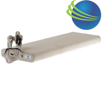
Antenna type : Yagi
Operating frequency range : 2400 - 2485 MHz
VSWR : < 1.5:1 (VSWR)
Gain : 10 dBi
Polarization : Vertical or horizontal, linear
Cable length and type : 3 ft. (0.91 m) low los
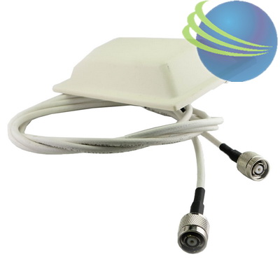
Cisco Aironet 2.4GHz Pillar Mount Antenna, AIR-ANT3213
Model Number : AIR-ANT3213
Manufacturer : Cisco
Availability : 2 in stock
Frequency Range :2.4GHz
Gain :5.2 dBi
Wireless Standards
Weight :0.99 lbs
Antenna type : Dipole
Operating frequency range : 2.4- to 2.84-GHz
Environment : Indoor/outdoor
VSWR : Less than 2:1, 1.5:1 nominal
Gain : 5.2 dBi
Polarization : Linear, vertical
E-Plane (3dB bandwidth) : Omnidirectional