Giá:
3,625,200 VNĐ
(Giá chưa bao gồm VAT )
Bảo hành: 12 (Tháng)
Tình trạng:
Hàng mới
Nhóm: Thiết bị wifi -» Accessories
Trong kho:
Còn hàng - 1 Cái
Xuất sứ: Chính Hãng
Chi tiết
Thông số kỹ thuật
Download
Phản hồi khách hàng
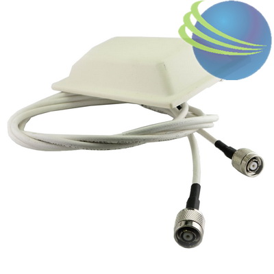
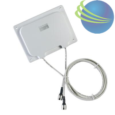
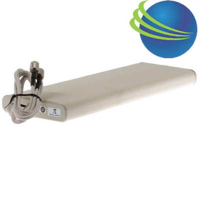
Cisco Aironet 6-dBi Patch Antenna
Antenna type: Single patch
Operating frequency range: 2400 - 2484 MHz
Nominal input impedance: 50W
2:1 VSWR bandwidth: 2400 - 2484 MHz
Peak gain: 6.0 dB
Po
Learn more about the Cisco Systems, Inc. AIR-ANT2460P-R
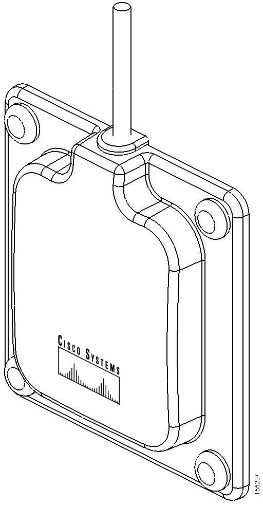
This document outlines the specifications, describes the AIR-ANT2460P 6-dBi patch antenna, and provides instructions for mounting it. The antenna operates in the 2.4-GHz frequency range and is designed for use in both indoor and outdoor environments.
The following information is provided in this document.
36 in. (91.4 cm)
Times AA-9303 or equivalent (plenum rated)
Connector type
RP-TNC
Length
4 in. (10.1 cm)
Width
3.6 in. (9.1) cm)
Height
1 in. (2.5 cm)
Operating temperature range
-22°F to 158°F (-30°C to 70°C)
Storage temperature range
-40°F to 185°F (-40°C - 85°C)
UL2043 compliant
Yes
Environment
Indoor/outdoor
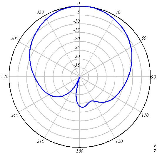
E-Plane Pattern
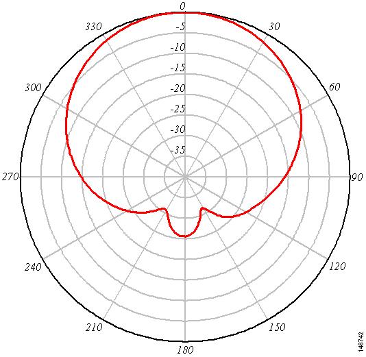
H-Plane Pattern
System Requirements
This antenna is designed for use with Cisco Aironet access points and bridges but can be used with any 2.4-GHz Cisco Aironet radio device that utilizes an RP-TNC connector.
Safety Precautions
Translated versions of the following safety warnings are provided in the Safety Warnings for Cisco Aironet Antennas, which is available at http://www.cisco.com.
Warning This warning symbol means danger. You are in a situation that could cause bodily injury. Before you work on any equipment, be aware of the hazards involved with electrical circuitry and be familiar with standard practices for preventing accidents. Use the statement number provided at the end of each warning to locate its translation in the translated safety warnings that accompanied this device. Statement 1071
SAVE THESE INSTRUCTIONS
Warning In order to comply with RF exposure limits established in the ANSI C95.1 standards, it is recommended when using a laptop with a PC card client adapter that the adapter's integrated antenna is positioned more than 2 inches (5 cm) from your body or nearby persons during extended periods of transmitting or operating time. If the antenna is positioned less than 2 inches (5 cm) from the user, it is recommended that the user limit exposure time. Statement 254
Warning Do not work on the system or connect or disconnect cables during periods of lightning activity. Statement 1001
Warning Do not locate the antenna near overhead power lines or other electric light or power circuits, or where it can come into contact with such circuits. When installing the antenna, take extreme care not to come into contact with such circuits, because they may cause serious injury or death. For proper installation and grounding of the antenna, please refer to national and local codes (for example, U.S.:NFPA 70, National Electrical Code, Article 810, Canada: Canadian Electrical Code, Section 54). Statement 1052
Each year hundreds of people are killed or injured when attempting to install an antenna. In many of these cases, the victim was aware of the danger of electrocution, but did not take adequate steps to avoid the hazard.
For your safety, and to help you achieve a good installation, please read and follow these safety precautions. They may save your life!
1. If you are installing an antenna for the first time, for your own safety as well as others, seek professional assistance. Your Cisco sales representative can explain which mounting method to use for the size and type antenna you are about to install.
2. Select your installation site with safety, as well as performance in mind. Remember: electric power lines and phone lines look alike. For your safety, assume that any overhead line can kill you.
3. Call your electric power company. Tell them your plans and ask them to come look at your proposed installation. This is a small inconvenience considering your life is at stake.
4. Plan your installation carefully and completely before you begin. Successful raising of a mast or tower is largely a matter of coordination. Each person should be assigned to a specific task, and should know what to do and when to do it. One person should be in charge of the operation to issue instructions and watch for signs of trouble.
5. When installing your antenna, remember:
a. Do not use a metal ladder.
b. Do not work on a wet or windy day.
c. Do dress properly—shoes with rubber soles and heels, rubber gloves, long sleeved shirt or jacket.
6. If the assembly starts to drop, get away from it and let it fall. Remember, the antenna, mast, cable, and metal guy wires are all excellent conductors of electrical current. Even the slightest touch of any of these parts to a power line complete an electrical path through the antenna and the installer: you!
7. If any part of the antenna system should come in contact with a power line, don't touch it or try to remove it yourself. Call your local power company. They will remove it safely.
8. If an accident should occur with the power lines call for qualified emergency help immediately.
Installation Guidelines
Because the antenna transmits and receives radio signals, they are susceptible to RF obstructions and common sources of interference that can reduce throughput and range of the device to which they are connected. Follow these guidelines to ensure the best possible performance:
•Mount the antenna to utilize its propagation characteristics. One way to do this is to orient the antenna vertically and mount it as high as possible.
•Keep the antenna away from metal obstructions such as heating and air-conditioning ducts, large ceiling trusses, building superstructures, and major power cabling runs. If necessary, use a rigid conduit to lower the antenna away from these obstructions.
•The density of the materials used in a building's construction determines the number of walls the signal must pass through and still maintain adequate coverage. Consider the following before choosing the location to install your antenna:
–Paper and vinyl walls have very little affect on signal penetration.
–Solid and pre-cast concrete walls limit signal penetration to one or two walls without degrading coverage.
–Concrete and wood block walls limit signal penetration to three or four walls.
–A signal can penetrate five or six walls constructed of drywall or wood.
–A thick metal wall causes signals to reflect off, causing poor penetration.
–A chain link fence or wire mesh spaced between 1 and 1 1/2 in. (2.5 and 3.8 cm) acts as a harmonic reflector that blocks a 2.4-Ghz radio signal.
•Install the antenna away from microwave ovens and 2-GHz cordless phones. These products can cause signal interference because they operate in the same frequency range as the device your antenna is connected to.
•Install the antenna in avertical orientation to maximize signal propagation.
Site Selection
Before attempting to install your antenna, determine where you can best place the antenna for safety and performance.
Follow these steps to determine a safe distance from wires, power lines, and trees.
Step 1 Measure the height of your antenna.
Step 2 Add this length to the length of the structure on which you are mounting the antenna and then double this total for the minimum recommended safe distance.
Caution If you are unable to maintain this safe distance, stop and get professional help.
Generally, the higher an antenna is above the ground, the better it performs. Good practice is to install your antenna about 5 to 10 ft (1.5 to 3 m) above the roof line and away from all power lines and obstructions. If possible, find a mounting place directly above your wireless device so that the lead-in cable can be as short as possible.
Installing the Antenna
You can install the antenna on any indoor or outdoor flat vertical surface. Hardware for mounting the antenna on drywall is provided. If you intend to install your antenna on another surface, you must provide the appropriate hardware.
Note Four mounting screws are provided to mount the antenna. To ensure a safe, reliable, and long-standing installation, you must use all four screws to mount the antenna.
Note If you install the antenna outdoors, follow the instructions printed on the back of the antenna.
Tools and Equipment Required
An installation kit is shipped with the antenna and consists of the following hardware:
•Four #8 x ¾ Phillips head screws
•Four #8 plastic anchors
•Four end caps
You need the following tools and equipment, which are not provided.
•A Phillips screwdriver
•A drill
•A #29 ((0.136-in (3.45 mm)) drill bit (For drywall installation, other surfaces may require a different size)
•A small mallet or hammer
Mounting on a Vertical Surface
This procedure describes mounting the antenna on a drywall surface. If you are mounting the antenna on any other type of surface, your procedure may vary slightly. For indoor installations, you can mount the antenna so that the antenna cable is pointing up or down.
Follow these steps to mount your antenna on a vertical surface.
Step 1 Determine the location where you will mount the antenna.
Step 2 Use the antenna as a template to mark the locations of the four mounting holes.
Step 3 Use a drill and #29 drill bit to drill four holes at the locations you marked in Step 2.
Step 4 Start a plastic anchor into each hole.
Step 5 Use a mallet or small hamer to seat the anchors into the wall.
Step 6 Align the antenna's mounting holes with the anchors.
Step 7 Start a #8 x ¾ screw into each antenna mounting hole.
Step 8 Use a Phillips screwdriver to secure the antenna to the wall. Do not overtighten.
Step 9 Install the end caps into the antenna mounting holes.
Step 10 Remove the yellow installation warning label from the antenna radome.
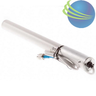
Antenna type : Yagi
Operating frequency range : 2400 - 2485 MHz
VSWR : < 1.5:1 (VSWR)
Gain : 10 dBi
Polarization : Vertical or horizontal, linear
Cable length and type : 3 ft. (0.91 m) low los
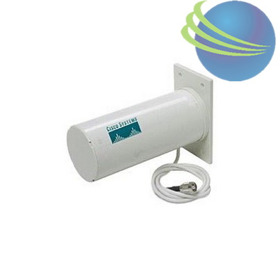
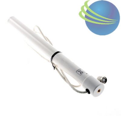
Cisco Aironet 2.4GHz Pillar Mount Antenna, AIR-ANT3213
Model Number : AIR-ANT3213
Manufacturer : Cisco
Availability : 2 in stock
Frequency Range :2.4GHz
Gain :5.2 dBi
Wireless Standards
Weight :0.99 lbs
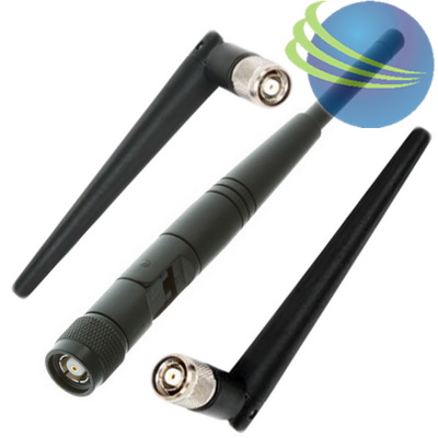
Antenna type : Dipole
Operating frequency range : 2.4- to 2.84-GHz
Environment : Indoor/outdoor
VSWR : Less than 2:1, 1.5:1 nominal
Gain : 5.2 dBi
Polarization : Linear, vertical
E-Plane (3dB bandwidth) : Omnidirectional


 Call
Call
 2,299,000 VNĐ
 2,200,000 VNĐ
 299,900 VNĐ
 1,190,000 VNĐ
 690,000 VNĐ
 1,490,000 VNĐ
 2,499,000 VNĐ